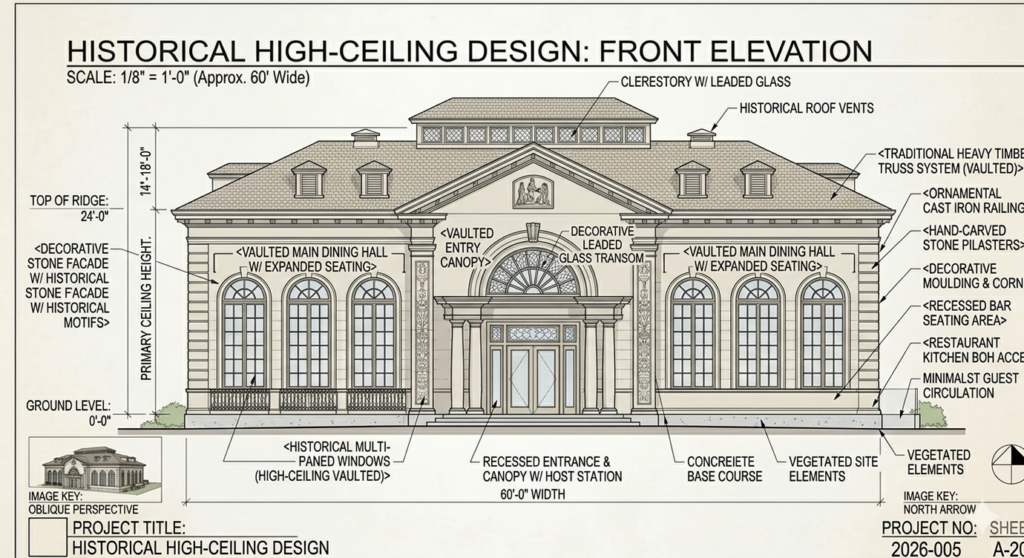
This architectural elevation presents a Historical High-Ceiling Design, blending the grandeur of a late 19th-century civic building with the functional requirements of a luxury modern restaurant. This design is perfect for a “Heritage Steakhouse” or a formal “Fine Dining” concept where the architecture serves as the primary marketing tool.
Design Highlights for a Restaurant Concept
- Grand Sense of Arrival: The central Vaulted Entry Canopy with its decorative leaded glass transom and stone columns creates an immediate “black-tie” feel. It establishes a clear, prestigious transition from the street to the host station.
- The “Clerestory” Light Well: A standout feature is the rooftop clerestory with leaded glass. This allows natural light to filter down into the center of the building, illuminating the main bar or a central “grand table” area even in deep-plan layouts.
- Symmetry and Grandeur: The mirrored layout—with high-arched, multi-paned windows on either side—creates a balanced, classical interior. These 18-foot-high windows offer diners a panoramic view of the street while providing passersby a glimpse of a high-end, candlelit atmosphere.
- Artisanal Detailing: The use of Hand-Carved Stone Pilasters and Ornamental Cast Iron Railings provides tactile quality. These historical motifs signal to guests that the restaurant values tradition, craft, and permanence.
- Vaulted Interior Volume: Despite being a single story, the 24-foot ridge height allows for a dramatic interior. The “Historical Multi-Paned Windows” suggest an interior with soaring ceilings, likely featuring crown molding or coffered plasterwork.
Operational Advantages
- Visual Zoning: The architectural symmetry makes it easy to divide the 60-foot-wide space into two distinct dining rooms (e.g., a “Library Lounge” on the left and a “Grand Dining Room” on the right).
- Discrete Back-of-House: The design includes a dedicated Kitchen BOH Access point that is architecturally integrated, ensuring deliveries and service staff movements do not disrupt the guest experience at the front.
- Climate & Light Control: The clerestory and high ceilings provide natural ventilation and light, potentially reducing energy costs for daytime service while maintaining a moody, upscale vibe at night.
To show you how that Historical elevation translates to a functional, grand restaurant, let’s explore the flow of the 60′ x 100′ footprint. The 100-foot depth (compared to the previous 60×80 designs) allows us to create distinct, luxurious, and massive social zones under that soaring 24-foot roofline.
Based on the [Image Key: Front Elevation] for the Historical High-Ceiling Design (Sheet A-202), here is the functional layout:
Level 1: The Main Stage (Ground Floor) – 6,000 Total Sq Ft
Vibe: Sophisticated, timeless, and dramatic, with 18’+ ceilings throughout all public areas.
- 1. The Vestibule & Reception (Center): Located directly behind the
and stone columns. - Entrance Foyer (15′ x 10′): Defined by historical tilework, a pair of detailed double doors, and clear visibility of the grand hall.
- Host Station (10′ x 5′): Positioned just inside, guiding guests into the main space.
- 2. Main Dining (The Social Hub) (Left & Right): Flanking the central entrance, these areas utilize the
. - Grand Hall (35′ x 100′): Centered under the high roofline. This massive open-concept space can host 150–180 guests at a mix of large round ‘tables-of-the-day’ and 4-top seating.
- Visual Focus (The Clerestory): Tables in the center of the room are positioned directly under the rooftop <Clerestory W/ Leaded Glass>. This area acts as the ‘Great Hall’ and is perfect for large group dining or specialized tasting menus.
- 3. Feature Bar & Lounge (Center-Rear): Aligned behind the central entrance to maintain symmetry.
- Symmetrical Bar (30′ x 20′): A large, elegant island bar, split down the middle by the main path of travel. Barstools surround it, serving as a social hub. The backbar scales the wall, utilizing the full height for high-shelf displays.
- Bar Lounge (20′ x 25′): Positioned between the entrance and the bar, offering comfortable low-seating (lounge armchairs and coffee tables) for pre-dinner drinks.
- 4. Core Services & Back-of-House (Rear): Discrete operations, aligned behind the right-hand dining section.
- Primary Guest Restrooms (M/F ADA Compliant) (15′ x 20′).
- Management Office (10′ x 12′).
- Culinary Engine (BOH) – Open Kitchen (30′ x 35′): The kitchen is positioned so that diners in the right-hand hall can see the activity, aligned behind the <Recessed Entrance> logic. This creates a functional yet visually transparent operational zone.
- Support areas: (Prep, Storage, Warewashing, Walk-in Cooler, Receiving).
Visualizing the Spatial Flow
The building functions as a vast, connected volume. While everything is on one floor, the clerestory light well creates a central, natural dividing point. Customers can look from one side to the other, or from the entrance to the bar, always seeing a soaring, light-filled space. This is the optimal layout for combining a grand historical experience with high-capacity, sophisticated dining operations.
To visualize this, we are looking at a 3D Longitudinal Section Cut. We have cut the building in half down its 100-foot length and are looking at it from the side, revealing how the vertical volume functions:
3D Cross-Section: The “Great Hall” Effect
The 3D cut shows that the building is not a series of flat-ceiling rooms, but a vast, continuous “cathedral-like” volume. The 24-foot peak height creates a dramatic sense of scale that is immediately apparent from the entrance.
- 1. The Light Well (Clerestory): The most critical design element is the central <Clerestory W/ Leaded Glass>. The visualization shows how sunlight (represented by warm, angled beams) filters down from the very top of the ridge, passing through the leaded glass. This illuminates the center of the 60′ x 100′ floor plan, which would otherwise be dark, highlighting the Feature Bar as a central social hub.
- 2. Symmetrical Dining Halls (Left & Right): The cut reveals the two primary dining zones under the <Vaulted Main Dining Hall W/ Expanded Seating> call-out. Because they are open to the central volume, they feel connected and massive. The high ceilings allow for grand chandeliers to hang 15 feet above the tables.
- 3. The Entresol/Office (Rear Loft): The visualization shows a clever use of the high volume at the rear. Above the Management Office and part of the Culinary Engine (BOH), a small, open “entresol” or mezzanine office is visible. This allows management to oversee the entire dining floor from above without disrupting the guest experience.
- 4. Functional Transparency: The cut clearly separates the <Recessed Entrance & Canopy W/ Host Station> from the active <Culinary Engine (BOH) – Open Kitchen Line>. Diners in the right-hand hall can see the activity, while those in the left are shielded, providing two distinct dining experiences within one 6,000 sq ft space.
This 3D view confirms that the historical grandeur is not just skin deep; it defines the entire volume and atmospheric quality of the restaurant
To show you how that Historical elevation is constructed, here is the detailed architectural joinery diagram for the Traditional Heavy Timber Truss System, focusing on the central Great Hall volume.
This drawing is a Large-Scale Section & Detail on Sheet A-501, using a scale of 1-1/2″ = 1′-0″ to show the precision required for these 18’+ ceilings.
Joinery Detail: The Traditional Heavy Timber Truss System
This diagram focuses on how the massive, load-bearing wood members are connected to create the open, vaulted space seen in the Front Elevation. The primary goal of this truss is to clear-span the 60-foot width of the Grand Dining Hall without needing internal support columns.
- 1. Key Components Labeled:
- <KING POST TRUSS (TIMBER)>: The central, dominant truss type that defines the ridge line.
- <TOP CHORD (6×10 TIMBER)> & <BOTTOM CHORD (8×12 TIMBER)>: The massive diagonal and horizontal members that take the main tension and compression loads.
- <KING POST (8×8 TIMBER)> & <STRUTS (6×6 TIMBER)>: The vertical and angled internal supports that stiffen the truss assembly.
- 2. Traditional Mortise & Tenon Joinery:
- The diagram highlights the specific interlocking connections that give the system its strength and historical authenticity.
- <MORTISE & TENON JOINT W/ DRAW-BORE PEGS> call-out: Shows how the diagonal Strut connects to the Bottom Chord. This traditional method, which uses wood pegs driven through offset holes to “draw” the joint tight, eliminates the need for modern steel plates and maintains the historical aesthetic.
- <RAFTER-TO-TOP CHORD CONNECTION W/ BIRD’S MOUTH CUT> call-out: A detail showing how the common rafters sit precisely on the main Top Chord, creating a flat surface for the roof decking.
- 3. Integrated Design Elements:
- The joinery diagram shows how the structure and the architecture merge.
- <CLERESTORY W/ LEADED GLASS (INTEGRATED CURB)>: A call-out detailing how the rooftop clerestory (which illuminates the bar below) sits directly on a structural curb built into the peak of the King Post Truss. This ensures the light well is stable and watertight.
- <DECORATIVE TIMBER PURLINS> & <HISTORICAL CROWN MOULDING (WOOD)>: Show how the exposed structure is finished to create the formal, “Great Hall” atmosphere, integrated directly with the supporting truss.
- 4. Loading & Connection Detail (Right):
- The diagram includes a separate detail focusing on the Truss Bearing & Connection to Stone Wall.
- <8×12 BOTTOM CHORD TRUSS BEARING ON BEARING PLATE> call-out: Shows how the massive Bottom Chord connects to a steel bearing plate set into the top of the historical stone wall, ensuring the 60-foot clear span is securely anchored.
- <DECORATIVE STONE FACADE W/ HISTORICAL MOTIFS> call-out: Puts the joinery detail in context with the external facade elements seen on Sheet A-202.